Official description
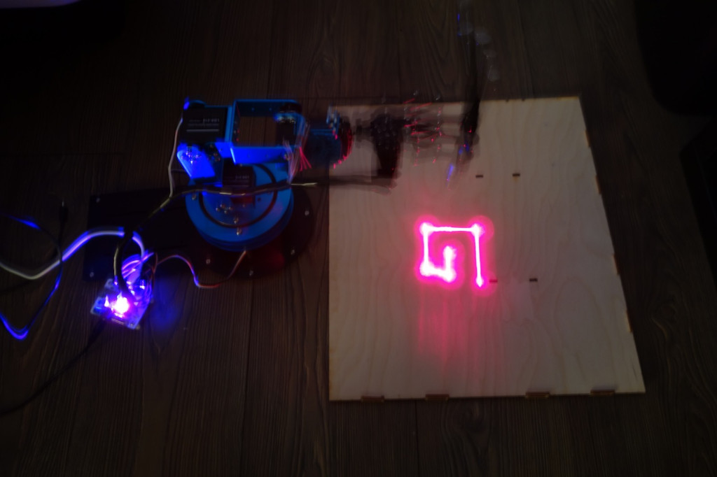
You can see pictures of a robot arm laser engraver attached. Can you figure out what it is engraving?
Note: the flag should be entered all in upper case. It contains underscores but does not contain dashes.
Good luck!
We are given a ZIP file containing engraver.pcapng, robot.jpg and robot_engraving.jpg
Exploration
USB capture
Let’s start by opening engraver.pcapng in Wireshark. We discover USB traffic.
As the capture was started before connecting the device, it contains the USB
device initialization:
GET DESCRIPTOR DEVICEresponse indicates a STMicroelectronics LED badge, mini LED display, 11x44 (ID0x0483:0x5750).GET DESCRIPTOR CONFIGURATIONresponse indicates that this device only has one USB HID interface with no standard subclass (0x00).- Then the host fetches some USB descriptors string:
0x01: MindMotion SOC Solutions0x02: Hiwonder0x03: MM32F103RB
The remaining packets of the capture correspond to HID data transfers as Wireshark does not include a dissector for this device.
Robot arm identification
The USB capture indicates MindMotion SOC Solutions Hiwonder MM32F103RB.
The pictures robot.jpg
and
robot_engraving.jpg
show a 6-axis blue robot holding a laser pointer.
With a bit of online search, we find that this robot is the LeArm by Hiwonder. More search indicates that we can interface with robot with https://github.com/ccourson/xArmServoController library.
Proposed solution
We extract the HID data from the USB capture and dissect it by analysing xArmServoController source-code. We notice that only 3 servomotors are used to draw, which means we don’t need to compute a reverse kinematic model of the arm. We finally plot the letters the robot was drawing during the USB capture and get the flag.
HID data dissection
We write a Python script to extract HID data using Scapy. We skip a fixed header defined in xArmServoController/xarm/controller.py.
| |
We get 418 combinations of durations, servomotor identifier and position:
500 1 2300
1500 2 1300
1500 3 1700
[...]
1500 4 2500
1500 5 1600
1500 6 1500
(Not) computing inverse kinematic
A first look at the previous data can be scary as we notice that all 6 servomotors are being driven. This means that we might need to compute a inverse kinematic model of the arm to get the pointer position and orientation from this data. After looking more closely, we notice 43 repetitions of a position reset pattern:
500 1 2300
1500 2 1300
1500 3 1700
1500 4 2500
1500 5 1600
1500 6 1500
Let’s replace this pattern by 0.
We now notice that only servomotors 1, 2 and 3 are being driven.
Servomotor 1 is always moving between position 2300 and 2400. A look at
the LeArm documentation reveals that it is the gripper. On the provided pictures
this gripper is positioned on the laser pointer button.
Servomotor 1 turns on and off the laser pointer.
We can consider a 2-axis drawing robot using the pan and tilt of the gripper.
Plotting the letters
We write the following Python script that computes the arm state after each command and then plot each succession of movements between resets:
| |
This script is imperfect as it does not consider timing and persistence of vision, but it was enough to flag this challenge.
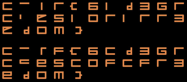
We recognize “fr3edom” at the end of the flag, which after a bit of thinking led
to CTF{6_D3GREES_OF_FR3EDOM}.